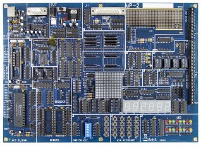
uP-2 MCU/PIC/AVR Training Board Kit
MCS 8051 / AVR / PIC MCU Board Training Kit
Introduction
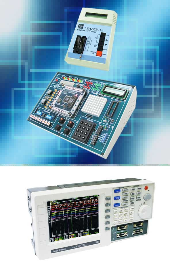
uP-2 microcontroller MCU training kit is including MCS-51, AVR and PIC, which are the top 3 popular Microcontroller MCUs on the market. The MCU training kit platform is flexible. Each part of the experiments has their own circuit unit. You can combine the experimental example or designated topic circuit to your own subject. uP-2 is the best platform for learning MCU.
Features
- Applied subjects are including MCS-5X/AVR/PIC16F8XX.
- Available for 20 or 40 pin MUC.
- Compatible with many brands of emulators.
- System is designed on stand-alone CPU, interface separately.
- Provides 26 circuit units.
- All of the circuits are able to combine cable wires by users.
- No need to Solder, saving time.
- 385 holes on the board which provide users with extended application or subjective experiments.
- The Power is provided with two kinds of input, 9V adaptor or DC 9V.
Circuit Unit
- 20 & 40 pin MCS-51/AVR IC socket
- 20 & 40 pin PIC16F8XX IC socket
- USB
- RS-232
- Printer port
- EPROM/FLASH socket for program extension, up to 512K x 8bits
- SRAM socket for program extension, up to 512K x 8bits
- IO decoder
- Red/yellow/green LED
- 6 digits 7 segment display
- Stand-alone push button x 4
- DIP switches
- 16×16 two colors dot matrix LED
- System power supply
- A/D ADC0804 IC
- D/A AD7528 IC
- LCD socket extension.
- OP LM324 IC
- Relay x 4
- Step Motor driver ULN2003
- 82C55 IO extension
- Buzzer output
- EEPROM 93C46 & 24C02
- Matrix keypad circuit x 16(4×4)
- Photo
- 385 hole universal board
Experimental Contents
- LED
- Push button
- Single and dual Traffic light control
- Neon lamp
- Extended program memory
- Extended data memory
- Extended EEPROM recode data
- 16×16 double color dot matrix display, Character/graph
- 6 digits dynamic 7 segment display LCD circuit (LCD is option)
- Step motor driver circuit (need connect to external motor)
- Relay control 4×4 matrix keypad scan circuit
- Press button circuit
- Touch switch read and set
- Timer
- Password key
- Electronic piano
- Counter
- A/D and D/A conversion
- 8255 I/O extension
- Multi I/O decode
- Serial Peripheral Interface
- Printer interface
- USB interface
- USB transfer to RS-232
- OPTO input & output
Specification
- Operating System: Windows 8 32/64bits, Windows 7 32/64bits, Windows VISTA 32/64bits, Windows XP 32/64bits
- Communication: Printer / RS-232 / USB Port
- Power: 9V DC Adaptor / 9V DC Extend Power Pin
- Dimension: 316 mm x 222mm x 2.1cm
- Weight: 700g

